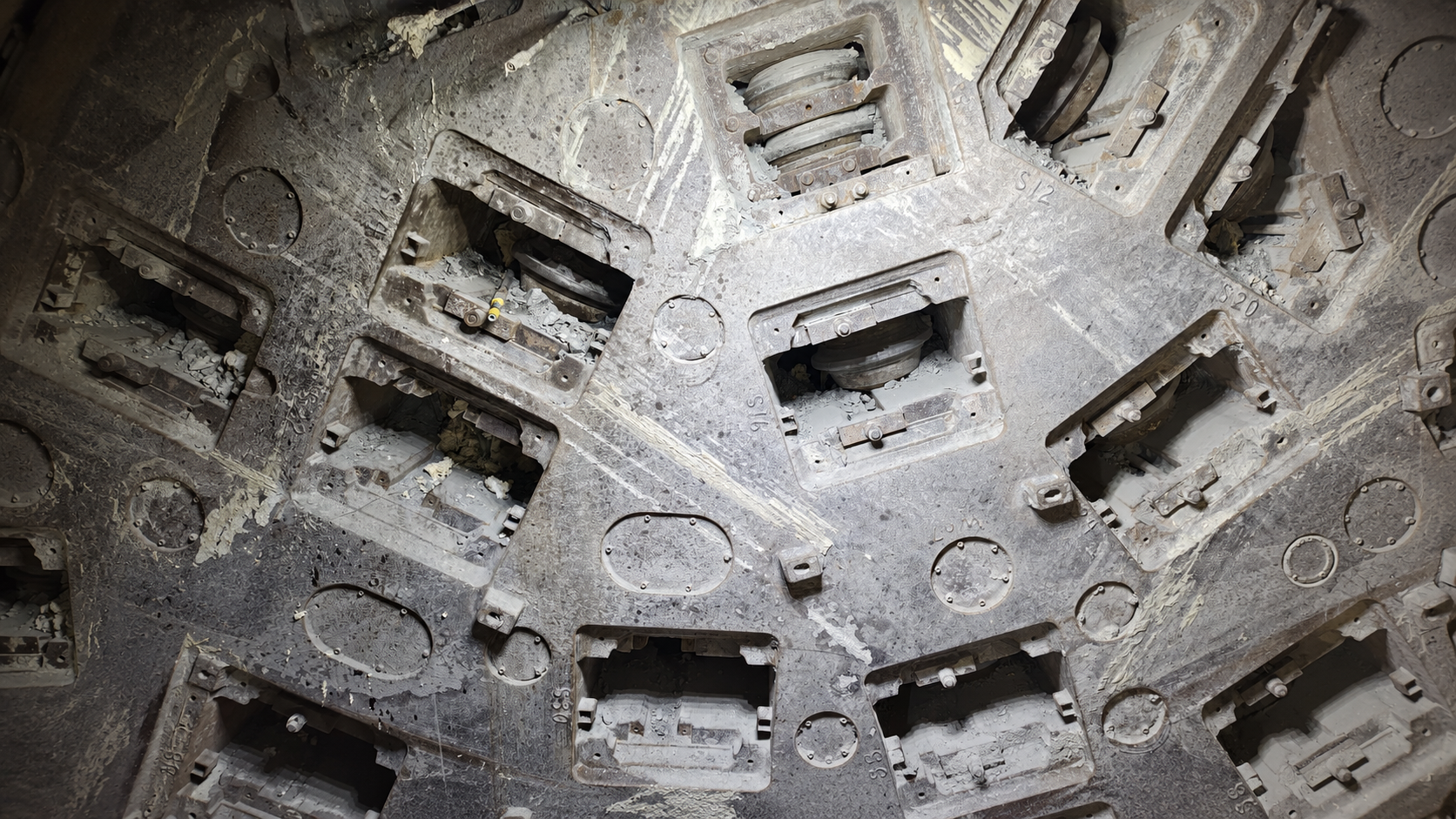
A TBM disc cutter is a complete engineering system. Its performance—and its failure—is never caused by a single factor. Geological conditions, cutter position, operating parameters, component quality and maintenance decisions all interact. For project teams, the real challenge is not understanding any one of these pieces, but connecting them: recognising what wear is telling you, judging whether a cutter can remain in service, and knowing when to replace, refurbish, or adjust the strategy at the cutterhead level.
This guide brings together the key principles from our technical series—component structure, wear patterns, selection logic and inspection practice—and integrates them into a framework for field decision-making.
A disc cutter consists of five key components working together as a system: the cutter ring breaks rock, the cutter hub provides structural support, the bearing assembly ensures smooth rotation, the sealing system protects internal components, and the cutter shaft transfers load. The load path is clear: rock → cutter ring → cutter hub → bearing assembly → cutter shaft → cutterhead. But the implications are not simple.
If the sealing system fails, grease leaks out and water and contaminants enter. The bearing then deteriorates, rotation becomes rough, and the cutter ring begins to slide instead of roll. What appears on the surface to be "cutter ring wear" may in fact be a seal or bearing problem that has already caused secondary damage.
Field implication: Do not judge a cutter solely by its ring wear. First confirm that rotation is smooth, that there is no grease leakage, and that axial and radial play are within specification. A cutter whose wear is still within limit but whose seal has failed is not a "good cutter"—it is a cutter that may fail at any time.
Not all wear is the same. Distinguishing normal consumption from abnormal damage is the basis of every replacement decision.
Condition What You See What It Usually Means
Normal / uniform wear Even material loss around the cutter ring circumference; gradual reduction in outside diameter Expected consumption; continue monitoring
Eccentric / flat wear Uneven ring profile; localized flat surfaces Restricted rotation, often due to bearing seizure or packed material
Cutting edge fracture Localized chipping or breakage along the cutting edge Impact loads, fractured ground, or insufficient toughness
Severe cutter ring fracture Cracks extending through the ring cross-section High impact, crack growth, or continued operation after damage
Cutter ring detachment Ring displaced or separated from the hub Progression of severe fracture; fit or assembly problems
Bearing failure Rough rotation, seizure, abnormal play Overloading, inadequate lubrication, contamination
Seal failure / leakage Grease loss; water or slurry ingress Worn sealing faces, trapped particles, installation problems
Key point: Similar symptoms may have different causes. A flat spot may be caused by bearing seizure, or by material packed around the cutter hub. The correct response depends on identifying the root cause, not merely observing the surface damage.
When a maintenance window opens, inspection should follow a consistent sequence. Based on our field inspection checklist, the basic workflow is as follows:
Remove loose material, mud and rock fragments around the cutter ring and cutter housing. Confirm the cutter number and cutterhead position. Center cutters, face cutters and gauge cutters work under different loads and wear differently. Record the excavation interval since the last inspection or replacement.
Use a model-specific wear gauge or a suitably sized vernier caliper. Measure at multiple points around the cutter ring circumference. Similar readings indicate uniform wear; large differences indicate eccentric or flat wear that an average value would conceal. Radial wear should be recorded consistently. When outside diameter is measured with a caliper, radial wear is calculated as:
Radial wear = (original outside diameter − measured outside diameter) ÷ 2
Compare the result with the allowable radial wear limit for that cutter model. Do not apply the wear limit of one 17-inch or 19-inch cutter directly to a cutter of a different design.
A cutter whose wear is still within limit may still be unsuitable for continued use because rotation is abnormal. Check for excessive tightness, looseness or uneven resistance, and where conditions permit, compare with similar cutters. Focus on:
A seized or rough-running cutter should be removed for inspection of the bearing, seal, shaft and internal condition. Continued sliding will quickly turn a rotation problem into severe flat wear.
After refurbishment and reassembly, the cutter should rotate evenly, and starting torque should be measured and recorded. A cutter that is excessively tight, loose or uneven in rotation should be dismantled and rechecked. Acceptable torque must follow the assembly specification for the relevant cutter, not a universal value.
Some conditions do not require lengthy wear calculation. When inspection reveals the following, the cutter should be removed for replacement or technical assessment as soon as possible:
Access conditions for cutterhead inspection, ground stability and the maintenance plan may limit the next inspection opportunity. If a cutter is approaching its wear limit, assess whether it is likely to remain serviceable until the next planned inspection. The decision should consider:
When the remaining margin is small and the next safe inspection is far away, preventive replacement may be reasonable. This is a project decision, not a universal wear value.
Compare the cutter with adjacent cutters. A large height difference will redistribute load, and similar abnormal wear at multiple positions may indicate a larger cutterhead or load distribution problem. If one cutter has severe flat wear or has stopped rotating, inspect adjacent positions for accelerated wear or impact damage. Replacing only the most visibly damaged cutter may not solve the overall problem.
Every inspection should end with one clear action for each cutter:
Continue in service — The cutter is within its specified wear limit, rotates normally, and has no unacceptable leakage, looseness or structural damage.
Continue with closer monitoring — The cutter remains within acceptance criteria but is approaching its wear limit, or shows a change that should be rechecked at the next available inspection.
Remove for refurbishment assessment — The cutter ring is worn, or bearing or seal problems are suspected, or another replaceable component has failed, while the cutter body and other load-bearing parts may still be serviceable. The final decision should be made after dismantling and inspection under the approved repair standard.
Replace the complete cutter — The cutter has reached its specified limit, cannot rotate normally, has unacceptable structural damage, or cannot safely remain in operation until the next inspection. A cutter with a cracked or deformed ring, or severely damaged load-bearing parts, may not be suitable for refurbishment.
Replacement decisions do not occur in isolation. They depend heavily on whether the cutter was correctly selected for the geological conditions in the first place.
Hard rock and abrasive ground requires strong wear resistance, adequate load capacity and reliable sealing performance. But maximum hardness is not always the best answer—an excessively hard cutter ring may be more prone to brittle cracking under impact loads.
Fractured and jointed ground prioritises toughness, impact resistance and assembly reliability. A balanced combination of toughness and wear resistance is usually more important than pursuing maximum hardness alone.
Mixed ground requires adaptability and overall system reliability, rather than optimising a single component for one rock type. Cutter ring material, bearing load capacity, sealing performance and cutter arrangement should be evaluated together.
Water-bearing or slurry-contaminated conditions place particular emphasis on floating seal reliability, grease retention and protection of the internal bearing system. Sealing performance cannot be considered separately from bearing quality and assembly accuracy.
Cutter position is equally important. Center cutters follow shorter cutting paths but carry concentrated loads near the cutterhead centre. Face cutters perform most of the rock-breaking work. Gauge cutters follow longer paths and also carry lateral forces associated with profile excavation. These differences affect wear rates and failure modes, and therefore the replacement strategy.
Consistent inspection records are the key to turning individual decisions into a controlled process. A practical record should include:
Over time, these records reveal wear trends, validate selection choices, and support better planning of inspection intervals and replacement strategies.
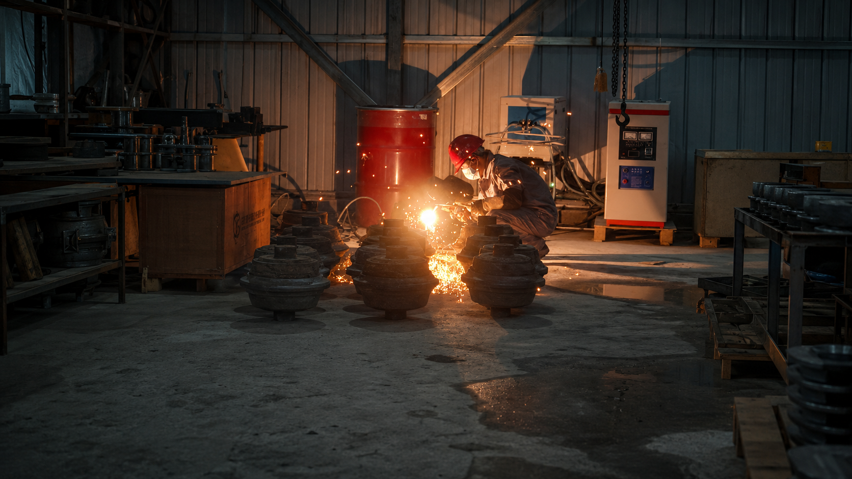
Operating data tells the team when to inspect; direct inspection determines what to do with the cutter. Measured wear, rotation condition, structural damage and the next safe inspection opportunity must be considered together, not judged in isolation.
A TBM disc cutter is not an ordinary consumable replaced on a fixed cycle. It is a system component whose condition should be assessed against its actual working environment. The projects that manage cutters most effectively are usually those that combine structured inspection, clear decision criteria, accurate records, and a selection strategy matched to the ground.




 Company Profile